
Just send us the CAD” is the most common sentence at the start of a device animation project, and it hides most of the risk. CAD, meaning computer-aided design, is the engineering data your product was designed in.
It contains everything needed to manufacture the device and very little of what is needed to render it. What happens between those two states determines your schedule, your budget, and whether the finished animation looks like your product. Here is what actually goes on in that gap.
Key Takeaways
- Send a neutral format export alongside your native files. STEP AP242 carries the most useful combination of geometry, structure and color.
- Never send STL for animation. It discards assembly structure, materials and surface accuracy in one step.
- CAD surfaces are mathematical. They have to be converted to polygons, and the tolerance setting on that conversion decides whether curves look smooth or faceted.
- Assembly mates and constraints do not survive export. Motion has to be rebuilt from scratch.
- CAD carries color, not materials. Anodizing, polymer translucency and surgical steel all need building.
- Unit and up-axis mismatches are silent failures that surface late, usually at lighting.
- Send one representative part before the whole assembly. It is the cheapest de-risking available.
Which File Format Should You Actually Send?
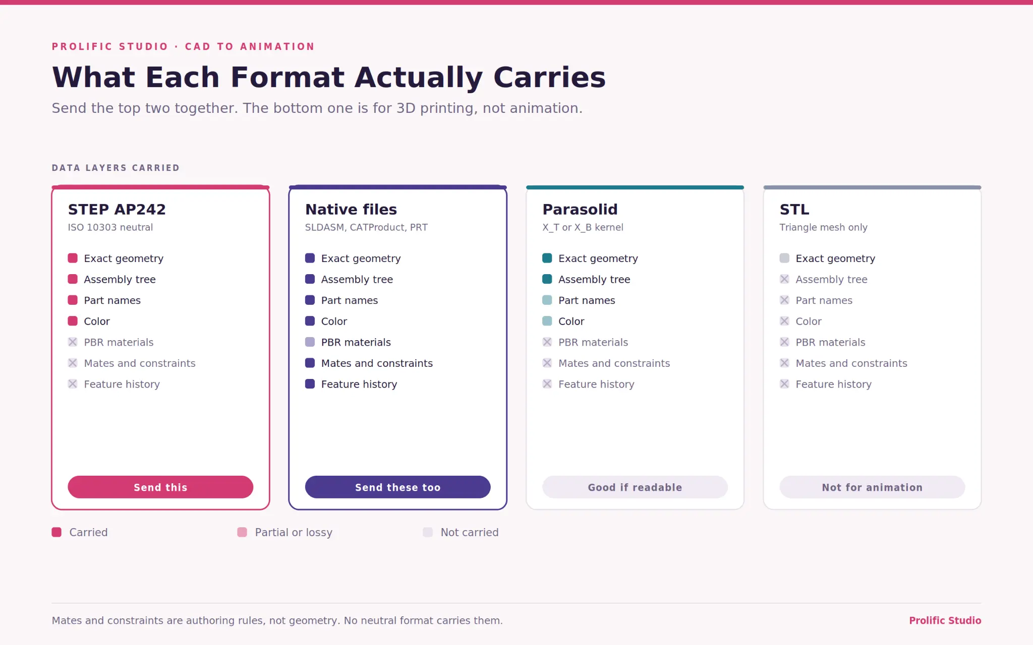
Send a STEP AP242 export plus your native files. That combination covers the most ground and costs you nothing extra.
The formats break down roughly like this. STEP, standardized as ISO 10303, is the workhorse. AP203 carries geometry and assembly structure, AP214 adds color and material references, and AP242 merges both and handles product manufacturing information.
Parasolid exports carry very high geometric fidelity if your studio can read them. IGES is older, surface-based, and prone to gaps that have to be repaired manually. JT is a lightweight visualization format, useful for review rather than production.
Native files matter too, because they preserve everything, including the feature history a studio may need if geometry has to be modified. Send both.
The format to avoid is STL. It is a triangle soup with no assembly structure, no materials, and a fixed tessellation baked in at export. Perfectly good for 3D printing, close to useless for animation.
Any provider of medical device animation services should tell you which of these they prefer before you send anything.
Why CAD Geometry Cannot Be Rendered As-Is
Because CAD describes surfaces with mathematics and renderers describe them with triangles. Those are not compatible, and the translation is lossy in one direction only.
Engineering CAD uses boundary representation, where a shape is defined by exact analytic and spline surfaces, commonly NURBS. A cylinder in CAD is a perfect cylinder, described by a radius and an axis, at infinite precision. It has no polygons because it does not need any.
Rendering engines and animation software work with polygon meshes. Every curved surface has to be approximated by flat facets before anything can be lit, shaded, or moved. That conversion is called tessellation, and it is where most of the visual quality problems originate.
The consequence is that geometric perfection in CAD does not transfer. What transfers is an approximation whose quality depends entirely on how the conversion was configured.
Setting Tessellation Tolerance So Curved Surfaces Do Not Look Faceted
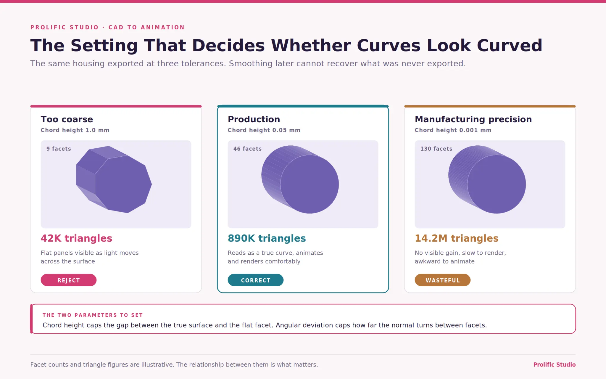
Two parameters do most of the work: chord height and angular deviation. Getting them wrong produces either a visibly polygonal device or a file too heavy to animate.
Chord height, sometimes called deviation, is the maximum distance allowed between the true mathematical surface and the flat facet approximating it. Tighter values mean more triangles and smoother curves.
Angular deviation limits how much the surface normal can turn between adjacent facets, which is what actually controls whether a curve reads as smooth under specular light.
The failure most people recognize is a cylindrical shaft or a rounded housing that shows visible flat panels when light moves across it. That is almost always an export tolerance problem rather than a modeling problem, and it cannot be fixed later by smoothing.
Over-tessellation is the opposite trap. Exporting at manufacturing precision can produce meshes in the tens of millions of triangles, which render slowly and animate badly for no visible benefit.
What Gets Stripped, and Who Decides
Roughly half of a typical assembly never appears on screen, and removing it is both a performance decision and a confidentiality one.
The usual candidates: internal electronics and circuit boards, fasteners and threaded features, internal ribbing and mounting bosses, seals hidden behind housings, and small fillets below the size a viewer could ever perceive. Screw threads in particular are expensive geometry that almost never earns its cost.
The decision should be yours rather than the studio’s, for two reasons. First, only your team knows which internal features might need to appear in a cutaway later. Second, internals you do not need on screen are often exactly the parts you would rather not send outside the building.
Practical approach: ask your engineering team for a simplified or “defeatured” configuration if your CAD system supports one. Many do, and it produces a clean export in minutes rather than requiring the studio to guess.
A medical animation studio experienced with device work will send back a list of what it proposes to remove before removing it.
Why Assembly Constraints Do Not Survive the Export
Because mates and constraints are authoring history, not geometry, and neutral formats carry geometry.
In CAD, a hinge rotates because a mate defines its relationship to the part it attaches to. That relationship lives in the assembly file as a rule, not as data attached to the shape. Export to a neutral format, and the parts arrive in the right positions with no memory of why they are there.
The consequence is that all motion has to be rebuilt. Pivot points get placed by hand, hierarchies get parented in the animation software, and any mechanism with constrained movement gets rigged from scratch. For a simple deployment this is an afternoon. For a multi-stage mechanism with linked components it is a genuine stage of work.
What does transfer, in a well-formed STEP file, is the assembly tree structure. The standards work behind that sits with ISO technical committee 184, subcommittee 4, which develops the product data exchange standards STEP belongs to.
Give every part a meaningful name before export. A hierarchy of “Part1, Part2, Part3” costs somebody hours of identification. The rigging stage parallels what our drug MOA animation process guide describes for molecular work.
Retopology or Decimation: Which Does Your Part Need?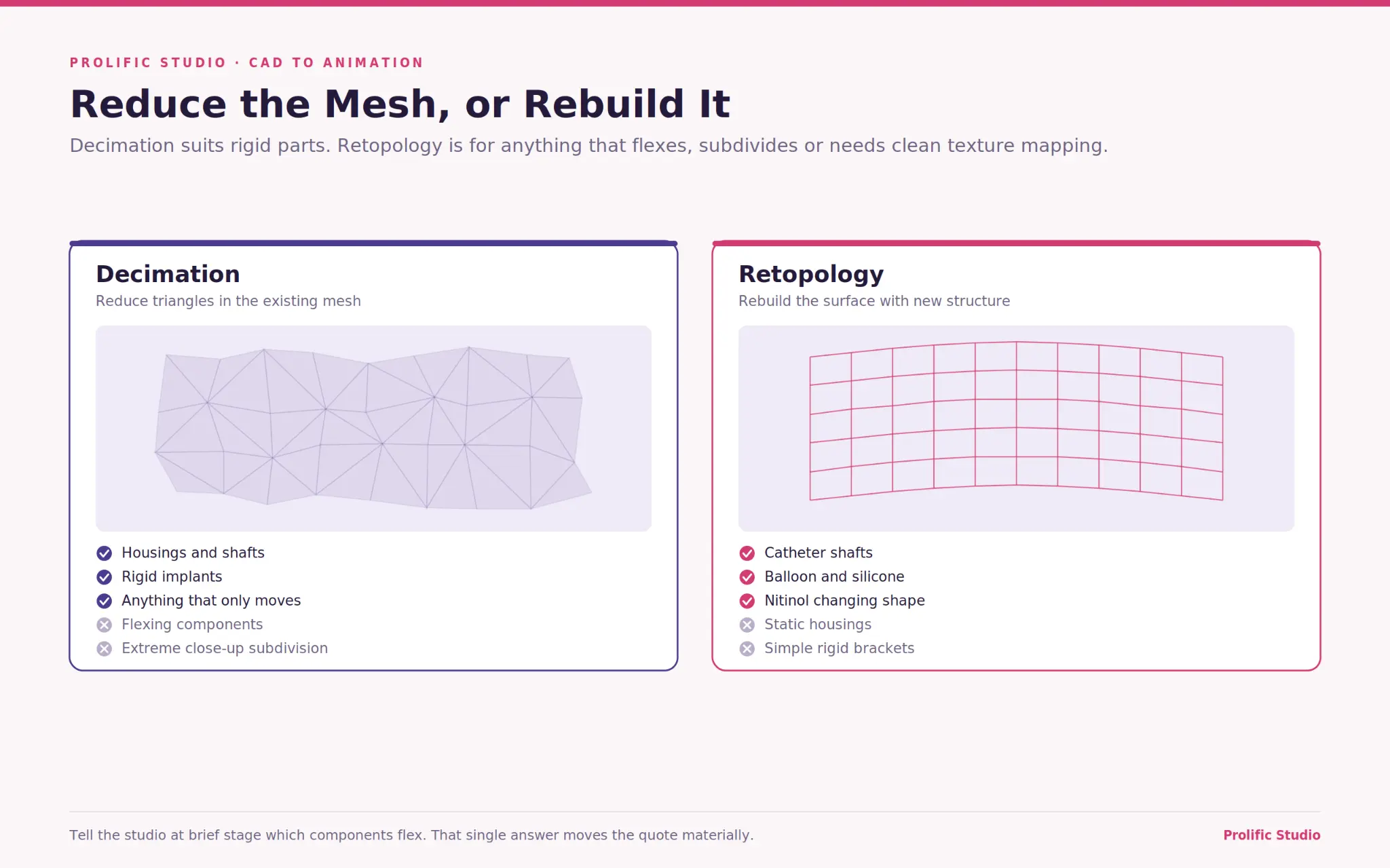
Decimation for most rigid device parts. Retopology when a surface has to deform, subdivide or carry clean UV mapping.
Decimation reduces triangle count in an existing mesh while trying to preserve silhouette. It is fast, largely automatic, and perfectly adequate for a housing, a shaft or a rigid implant that will only ever translate and rotate.
Retopology rebuilds the surface with new, deliberately structured geometry, usually quads following the form. It costs far more time, and it is necessary when a part flexes, when you need subdivision for extreme close-ups, or when texture mapping has to be clean across a complex surface.
Most device projects need decimation on the majority of parts and retopology on two or three. Flexible components are the usual candidates: catheter shafts, balloon materials, silicone seals, anything Nitinol that changes shape.
Being specific about which parts flex, at a brief stage, saves real money. A healthcare animation production company that asks which components deform before quoting is scoping accurately rather than optimistically.
Turning CAD Appearances Into Renderable Materials
CAD carries color. Rendering needs materials, and the gap between those two is bigger than it sounds.
A CAD appearance is typically an RGB value with a basic gloss setting. A physically based material needs base color, metallic and roughness values, normal detail, and often anisotropy for brushed or machined finishes. None of that is in your file.
Device materials are also unusually specific. Anodized aluminum reads differently from bare aluminum. Passivated stainless behaves differently from polished. PEEK, polycarbonate, and silicone each scatter light in their own way, and translucent polymers need subsurface treatment to avoid looking like painted plastic. Nitinol looks wrong if it is rendered as generic chrome.
Supply photographs of the real device if it exists, plus the finish specification. A photograph of a machined housing under normal light tells a lighting artist more than a color code does.
Delivery formats are increasingly standardizing around physically based descriptions, and the glTF specification maintained by the Khronos Group is the widely used open standard for transmitting that kind of material data downstream to web and interactive use.
Units, Scale and Up-Axis: The Silent Failures
These three cause more late-stage confusion than any other CAD issue, because nothing looks broken until it does.
CAD systems commonly work in millimeters. Animation software often defaults to different units, and most engineering packages treat Z as up while most animation packages treat Y as up. Import without checking, and you get a device that is either the wrong size relative to anatomy or lying on its side.
The size problem is the dangerous one, because it can look plausible. A stent modeled at ten times scale still looks like a stent. It stops looking right only once it is placed in a vessel, by which point several shots may have been built around it.
Real-world scale also matters for lighting. Physically based renderers calculate depth of field, light falloff and subsurface scattering from actual dimensions, so a model at the wrong scale produces subtly wrong lighting that is hard to diagnose.
Confirm units and up-axis in writing at handover, and ask the studio to verify against a known dimension before building anything. Scale errors surface at lighting, which is late and expensive in the pipeline our medical animation cost guide breaks down.
How Do You Protect CAD Files You Send Out?
With an agreement first, a reduced dataset second, and a controlled transfer method third. In that order.
CAD is among the most sensitive material a device company holds. It contains manufacturing details, tolerances, and design decisions that represent years of work, and for an unlaunched product it may also reveal timing you are keeping confidential.
Our guide on how 3D animation helps medical device product launches covers why pre-clearance secrecy matters commercially.
Four practical controls. Sign a confidentiality agreement before any file moves, not alongside the first invoice. Send a defeatured configuration rather than the full manufacturing dataset, which reduces exposure and file size at once.
Use a controlled transfer method rather than email attachments or consumer file sharing. And agree in writing what happens to the files at project end, including whether they are deleted or archived.
Ask about the studio’s internal handling too. Who has access, whether work happens on managed machines, and whether subcontractors are involved. A studio that has thought about this will answer immediately.
What Happens When Engineering Revises the Part Mid-Project
It happens on most projects, and the cost depends entirely on when.
Engineering change continues while animation is in production. A dimension moves, a component is redesigned, a supplier changes. If that happens before modeling, it costs a re-export. If it happens after animation and lighting, every shot the part appears in has to be revisited.
Three things reduce the damage. Agree a design freeze on the revision being animated, with a documented revision number, so everyone knows which version the film depicts. Name one person on the engineering side responsible for telling the studio when geometry changes. And identify early which parts are still moving, so the studio can sequence those shots last.
Also decide what happens if the product changes after delivery. If the film shows a superseded revision, you need to know whether the contract covers an update and what it costs.
Final Words
The single most useful thing you can do at the start is send one representative part, exported the way you intend to export the rest.
Pick something with a curved surface, a couple of sub-components and a typical finish. The studio converts it, renders a still and tells you what it found. Faceting, gaps, naming, scale, missing materials: all of it surfaces in a day instead of week three.
That test also converts a defensive quote into an accurate one, because file condition is the largest unknown in device animation pricing.
Send us a test part and tell us what the finished film has to do. Prolific Studio is a video animation agency working across device, mechanism, clinical data and patient material, and we will tell you what your files need before the schedule depends on them.
Frequently Asked Questions
What CAD format should I send for animation?
STEP AP242 as the neutral export, plus your native files. AP242 carries geometry, assembly structure, and color. Native files preserve everything else in case geometry needs modifying.
Why does my device look faceted when rendered?
The tessellation tolerance at export was too coarse. Chord height and angular deviation control how closely flat facets follow the true mathematical surface, and smoothing after the fact cannot recover detail that was never exported.
Can you animate straight from an STL file?
Not usefully. STL has no assembly structure, no materials, and a fixed tessellation baked in. It works for 3D printing and fails for animation.
Do our assembly mates transfer to the animation software?
No. Mates are authoring rules rather than geometry, so all motion is rebuilt. A well-formed STEP file does preserve the assembly tree, which is why part naming matters.
How do we stop our CAD leaving the building unprotected?
Confidentiality agreement signed before any transfer, a defeatured export rather than the full dataset, controlled file transfer, and a written agreement on deletion or archiving at project end.
What if engineering changes the part halfway through?
Cost depends on timing. Before modeling, it is a re-export. After lighting it means revisiting every shot the part appears in. Agree on a design freeze with a documented revision number and name one person responsible for flagging changes.